Help and Information

Mounting Position

Motovario Gearbox Mounting Position

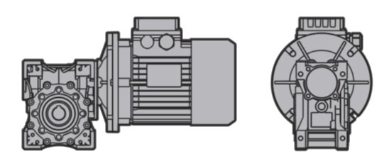
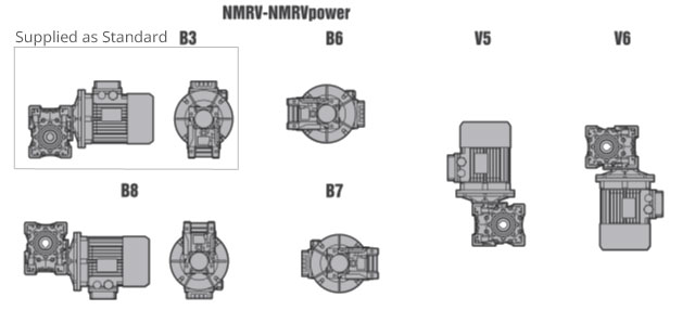
All geared motors and gearheads are supplied to be mounted in the B3 mounting position (as above) however sizes from NMRV/NMRV-P 025 - 030 - 040 - 050 – 063 - 075 it is not necessary to specify mounting position as they can be mounted in any position.

Sizes NMRV 090 – 110 – 130 – 150 the mounting position must be specified otherwise they will supplied for B3 mounting position only

Sizes 090 – 110 if mounted in position V5 or V6 they will need a special sealed bearing fitting. Please contact Transdrive application engineer

Warning

For sizes 090 and above mounting position is very important as the gearbox comes supplied with sufficient oil for mounting in B3 position only. Sizes 090 and above if a B3 unit is mounted in any other position then oil starvation to critical components will result in severe damage. Please do not hesitate to seek advice from one of our application engineers.

Full details of Mounting Positions can be found on page 40 of the PDF catalogue

NMRV  Mounting Options View Catalogue Page

Lubrication

For correct filling always refer to the sight glass or the dipstick, when this is supplied. Any oil level differences can be caused by constructive tolerances but also on the mounting position or the assembly scheme of the user. Therefore it is very important for the user to **check oil level and if necessary to add the necessary quantity.

The gear reducers size 025 - 030 - 040 - 050 – 063 - 075 - 090 - 110 are supplied complete with lubricant for life, synthetic oil, ENI TELIUM VSF.

The gear reducers size 130 – 150 are supplied complete with lubricant, mineral oil, AGIP BLASIA 460

***The gear reducers size 025 - 030 - 040 - 050 – 063 – 075 can be mounted in any position

***The gear reducers size 090 – 110 – 130 – 150 are supplied with oil suitable for mounting in B3 position only, any other position please contact Transdrive’s application engineers.

Sizes 090 – 110 if mounted in position V5 or V6 they need a special sealed bearing fitting. Please contact Transdrive application engineer.

Only reduction units 130 and 150 are fitted with breather, level and oil drainage plugs. It is necessary, after installation, to replace the closed plug used for transportation with the breather plug supplied with the unit.

Warning.

For sizes 090 and above mounting position is very important as the gearbox comes supplied with sufficient oil for mounting in B3 position only. If a B3 filled unit is mounted in any other position then oil starvation will occur resulting in critical damage to components. Please do not hesitate to seek advice from one of our application engineers.

**Full details of lubrication can be found on page 18 of the PDF catalogue

***Full details of Mounting Positions can be found on page 40 of the PDF catalogue

View Catalogue Page

Installation

To install the gear reducer it is necessary to note the following recommendations:

  • Check the correct direction of rotation of the gear reducer output shaft before fitting the unit to the machine.
  • In the case of particularly lengthy periods of storage (4/6 months), if the oil seal is not immersed in the lubricant inside the unit, it is recommended to change it since the rubber could stick to the shaft or may even have lost the elasticity it needs to function properly.
  • Whenever possible, protect the gear reducer against solar radiation and bad weather.
  • Ensure the motor cools correctly by ensuring good passage of air from the fan side.
  • In the case of ambient temperatures < -5°C or > +40°C call the Technical Service.
  • The various parts (pulleys, gear wheels, couplings, shafts, etc.) must be mounted on the solid or hollow shafts using special threaded holes or other systems that anyhow ensure correct operation without risking damage to the bearings or external parts of the units. Lubricate the surfaces in contact to avoid seizure or oxidation.
  • Painting must definitely not go over rubber parts and the holes on the breather plugs, if any.
  • For units equipped with oil plugs, replace the closed plug used for shipping with the special breather plug.
  • Check the correct level of the lubricant through the indicator, if there is one.
  • Starting must take place gradually, without immediately applying the maximum load.
  • When there are parts, objects or materials under the motor drive that can be damaged by even limited spillage of oil, special protection should be fitted.
View Catalogue Page

Service Factor

Service factor (f.s.) is a way of considering service life. A gearhead used in ideal conditions with uniform (normal duty), 8 hours per day running time and a maximum of 5 starts per hour has a service factor of 1, this gearhead can be expected to give in the region of 15,000 service hours use.

However if the gearhead is subjected to more arduous conditions and duty cycles then this can erode the service hours use, but it can be compensated in your selection by choosing the expected load of the gearbox in the filter selection area of the home page which will result in the correct size of gearhead being selected.

All selections in this site are based on 8 hours per day usage and a maximum of 5 starts per hour if your application exceeds these figures please speak to a Transdrive applications engineer who will gladly advise on the correct selection.

The service factor (f.s.) depends on the operating conditions the gearhead is subjected to.

The parameters that need to be taken into consideration to select the most adequate service factor Correctly are:-

Considerations:-

  • Type of load of the operated machine: A - B – C see below
  • Length of daily operating time: hours/day. All selections on this site are based on 8 hours usage per day.
  • Start-up frequency: starts/hour. All selections on this site are based on a maximum of 5 starts per hour.

LOAD

  • A - Uniform (Normal Duty)
  • B - Moderate shock Load
  • C - Heavy Shock Load

A - Uniform (Normal Duty)

Screw feeders for light materials, fans, assembly lines, conveyor belts for light materials, small mixers, lifts, cleaning machines, fillers, control machines.

B – Moderate Shock Load

Winding devices, woodworking machine feeders, goods lifts, balancers, threading machines, medium mixers, conveyor belts for heavy materials, winches, sliding doors, fertilizer scrapers, packing machines, concrete mixers, crane mechanisms, milling cutters, folding machines, gear pumps.

C - Heavy Shock Load

Mixers for heavy materials, shears, presses, centrifuges, rotating supports, winches and lifts for heavy materials, grinding lathes, stone mills, bucket elevators, drilling machines, hammer mills, cam presses, folding machines, turntables, tumbling barrels, vibrators, shredders.

For very heavy applications such as quarries and steel works please speak to a Transdrive application engineer who will gladly advise on the correct selection.

View Catalogue Page